Guest blog by Sujan Shrestha, PhD, Applications Engineer, Admiral Instruments

This is a guide for electrochemists interested in understanding and validating the DC accuracy of their potentiostats. To begin, it’s important to understand how to properly interpret the specifications of the potentiostat to calculate the expected accuracy of current and voltage measurements. Keep in mind that accuracy, precision, etc., also depend on the device under test (DUT). A reliable measurement can’t be obtained from a DUT whose electrochemical properties are in constant flux.
Key Measurement Concepts
To avoid confusion around the definition of accuracy, precision, resolution, and sensitivity, here are the definitions from the International Vocabulary of Basic and General Terms in Metrology (VIM), developed by the International Standard Organization (ISO), an international body responsible for developing standards:
- Quantity: Property of a phenomenon, body, substance, where the property has a magnitude and can be expressed as a number and a reference. (VIM 1.1)
- Measurand: Quantity intended to be measured. (VIM 2.3)
- Measurement Accuracy: Closeness of agreement between a measured quantity value and a true quantity value of a measurand. (VIM 2.13)
- Measurement Precision: Closeness of agreement between indications or measured quantity values obtained by replicate measurements on the same or similar objects under specified conditions. (VIM 2.15)
- Resolution of displaying device: Smallest difference between displayed indications that can be meaningfully distinguished. (VIM 4.15)
- Sensitivity of a measuring system: Quotient of the change in an indication of a measuring system and corresponding change in a value of a quantity being measured. (VIM 4.12)
What is specified as “accuracy” by the potentiostat manufacturer is the “uncertainty of measurement.” This is defined by VIM as a “non-negative parameter characterizing the dispersion of the quantity values being attributed to a measurand, based on the information used.” The real meaning of the uncertainty specification can only be known if we know how they are exactly determined. However, this is rarely explained to customers by the hardware manufacturer.
Most hardware manufacturers specify “accuracy” in terms of a range. It is generally understood that the accuracy (AKA measurement uncertainty) should be somewhere within this range. Moreover, it is also expected that the results from multiple trials should fall within that range given that other factors such as temperature remains the same. Therefore, the “accuracy” specification gives both “accuracy” and “precision” specifications of the potentiostat.
Basic Potentiostat Specifications for Current and Voltage
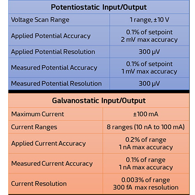
When using a potentiostat, having confidence in the accuracy of applied and measured voltage and current is what matters most. Applied and measured voltage and current accuracy and resolution is listed on the specification sheet for all potentiostats. Here’s an example of such a table for the Squidstat Solo potentiostat, which is the $1,900 USD entry-level potentiostat offered by Admiral Instruments. We will refer to these specifications later on for some example calculations.
While there are more specifications of the potentiostat, these are the most vital for validating DC performance:
- Maximum voltage
- Maximum current
- Applied voltage accuracy and resolution
- Measured voltage accuracy and resolution
- Applied current accuracy and resolution
- Measured voltage accuracy and resolution
Voltage and Current Ranges
Electrical instruments like potentiostats, multimeters, etc., divide their full current and voltage scale into smaller scales called ranges. This assures better “accuracy” and resolution across all values. The higher the number of ranges, the better the potentiostat’s “accuracy”, “precision,” and resolution.
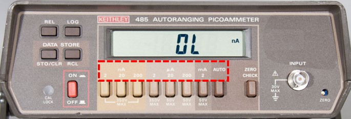
A range is named after its highest value. In this picture of the Keithley 485 picoammeter, seven current ranges can be seen within the red dotted area. These ranges are labeled as 2 nA, 20 nA, 200 nA, 2 µA, 20 µA, 200 µA, and 2 mA. The values of current measured in the 2 mA range are >200 µA and ≤2 mA.
Different Ways to Specify Accuracy
There is no universally standardized way to report voltage and current “accuracy” on an electronic instrumentation spec sheet. “Accuracy” is expressed in different ways by different instrument manufacturers.
- Admiral Instruments: X% of setpoint, Y max
- Admiral Instruments: X% of the range, Y max
- HP Digital Multimeter: ± (X% of reading + Y% of Range)
- Keithley Picoammeter: ± (X% of reading + Y offset)
- Fluke handheld multimeter: ± (X% of reading + Y count)
“Range” is also called Full-Scale (FS) or Full-Scale Range (FSR). Percentage (%) can also be expressed in parts-per-million (ppm). “Count” is the resolution of the multimeter.
If “accuracy” is specified in a different format between two similar devices, one must be careful to ensure that the context for the numbers provided is correctly interpreted.
Calculating Expected Voltage Accuracy
Here is an example for how to calculate the expected “accuracy” of applied and measured voltage signals from a potentiostat using our entry-level potentiostat mentioned before, the Squidstat Solo.
From the Squidstat Solo specifications sheet:
- The applied voltage accuracy is 0.1% of setpoint, 2 mV maximum
- The measured voltage accuracy is 0.1% of reading, 1 mV maximum
For example,
- If your setpoint is 1 V, 0.1% of 1 V is 1 mV. But the maximum possible accuracy is 2 mV, which is greater than 1 mV. Hence, the expected applied voltage is 1 V ± 2 mV.
- If your measured voltage is 8 V, 0.1% of 8V is 8 mV, which is greater than 1 mV. Hence the expected measured voltage is 8 V ± 8 mV.
Calculating Expected Current Accuracy
As with the previous voltage example, here is an example for how to calculate the expected “accuracy” of applied and measured current signals from a potentiostat using our entry-level potentiostat, the Squidstat Solo.
From the Squidstat Solo specifications sheet:
- The applied current accuracy is 0.2% of range, 1 nA max
- The measured current accuracy is 0.1% of range, 1 nA max
- Both the applied/measured current resolution is 0.003% of the range
The Squidstat Solo has 8 current ranges. The lowest range is 0 to 10 nA. Subsequent current ranges increase by decades. So, the second-lowest range is 10 nA to 100 nA, third-lowest is 100 nA to 1 µA, and so on.
- If your applied current setpoint is 5 nA, it falls within the lowest 0 to 10 nA range. 0.2% of this 10 nA full-scale range is 0.02 nA. However, this is lower than the maximum possible 1 nA accuracy. Hence the applied current is 5 nA ± 1 nA.
- If your measured current is 470 µA, it falls within the 100 µA to 1 mA range. 0.1% of this 1 mA full-scale range is 1 µ Hence the measured current is 470 µA ± 1 µA.
Validating Potentiostat Accuracy: Method 1 Using Resistors
Using a reliable reference object with suitably stable current/voltage characteristics is vital to validate whether or not a potentiostat or similar instrument is as accurate as expected. One such object type is the resistor. Resistors have linear current/voltage properties when used at stable temperatures. Resistors are also readily available and very cost-effective.
However, current and voltage accuracies cannot be independently determined using a resistor just by itself. Either the voltage or the current accuracy of the resistor needs to be determined beforehand.
When using a resistor to validate potentiostat accuracy, use resistors specifically designed for high drift tolerance. Also, the measured value of the resistor should be determined using a product or service that advertises a higher degree of accuracy than the potentiostat being validated. And remember to use a 4-wire connection to measure resistors with resistances <1 kOhm.
Once a reliable reference value has been established for the resistor being connected to the potentiostat, you can apply a current through the resistor. Now, the applied and measured current accuracy can be calculated based on the following equations.
Validating Potentiostat Accuracy: Method 2 with High-Precision Multimeters
For labs with high-precision multimeters in them that have ISO-certified calibration checks performed on a regular basis, this validation method is for you! It’s easier to use a programmable high-precision multimeter with greater accuracy than the potentiostats because both measured and applied accuracy can be determined with a single measurement and the validation process can be automated. Instead of multimeters, instruments specially designed to calibrate other instruments such as Fluke 5522A Multi-product Calibrator can also be used, but they are more expensive than typical high-precision multimeters.
Usually, the cables from the potentiostat can be directly connected to a multimeter. Sometimes, a resistor in series might be necessary to prevent cross-talk between the potentiostat and the multimeter. Both the potentiostat and the multimeter should be warm enough to maintain a stable reading. Please refer to the potentiostat and multimeter user manuals to see if they recommend a warm-up period before taking measurements. Also, you should allow for enough time between measurements for the readings to stabilize.
To determine the applied and measured voltage accuracy, apply a voltage (Set Value) through the potentiostat. The value shown by the multimeters (Multimeter Value) can be regarded as the “true” applied voltage, while the value shown in the potentiostat’s software is the measured voltage (Potentiostat Value). Now, the applied and measured voltage accuracy can be determined using equations below. Similarly, apply a current through the potentiostat to determine applied and measured current accuracy.
Our entire team at Admiral Instruments hopes this guide is helpful for any electrochemists to follow whenever they are wondering if their potentiostat readings are sufficiently accurate for the experiments being run!
ECS thanks Admiral Instruments for their support of the 240th ECS Meeting.


